Showing posts with label EXPERIENCES. Show all posts

Monday, June 25, 2018

https://maritime-engineering.blogspot.com/2018/06/main-machine-preparation-process-for.html

1. Check the fresh water temperature from M / E (62-65 o C) to adjust the heating temperature if needed.

2. Run the main pump (M / E L.O. pump), usually the pump is running.

 3. Rotate the cylinders of the cylinder about 70 - 80 times (remember the correct latch when finished)

4. Check that the main unit is fully open (if it is not open, open it)

5. Engage turning gear and turn on turning gear.

Check the L.O level of the M / E sumpt tank, the stern tube tank, the L.O. intermediate axis M / E, the M / E cylinder oil daily tank.

7. Check the L.O level of the L.O tank and lubricate the heater shaft, and run the O / B L.O cir pump (normally the pump is always running).

8. In the process of passing water leakage check on the combustion chamber of the M / E cylinders (if any), check whether there is something unusual in the engine

9. Check the water tank in the oil tank and the oil tank (F.O service tank F.O setting tank).

10. After 20-30 minutes, disengage turning gear and turn off turning gear, flush the bottles and fill up (if missing).

11. After the officer promoted, the discharge.

12. Check the water level in the expansion tank (F.W expansion tank), complement if missing.

13. During the preparation of the main engine, the combination of inspection and operation of other related equipment such as preparation of additional generators, parallel synchronization to prepare for maneuvering ship

Note: For each main engine and the main propulsion system of different ships, we add or subtract some of the steps required to complete the main engine. (Depending on the specific case we have. specific process). And on ship the process of preparing the machine is done by the oiler and the officer is the supervisor, support when needed.

Saturday, June 23, 2018

https://maritime-engineering.blogspot.com/2018/06/what-type-of-propeller-used-on-ship.htm

Procedure For Renew Propeller on ship
How to Measure Cylinder Liner Bore Wear on ship?
Types of Mechanical Measuring Tools and Gauges Used on Ships
what type of propeller used on ship? Controllable Pitch Propeller (CPP) Vs Fixed Pitch Propeller (FPP)?
Most of the propellers that are used in ships are fixed pitch propellers (FPP). What does this propeller term means? Let’s understand this from a beginner’s point of view.
If you look at a propeller axially, you will notice a twist in the propeller blade along the length of the propeller hub. It is this twist in the blade that results in the forward motion of the propeller with each rotation.
https://maritime-engineering.blogspot.com/2018/06/what-type-of-propeller-used-on-ship.htm
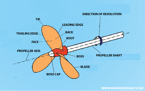
Parts of screw propeller
It is pretty much what you see on a screw. The angle of the thread is actually what is called the pitch angle. The more the pitch angle, the more distance is travelled by the screw in one rotation, that is, the more is the pitch. Similarly, propellers act on the principle of screw. Hence the term screw propeller.

But what is a fixed pitch propeller or the FPP?

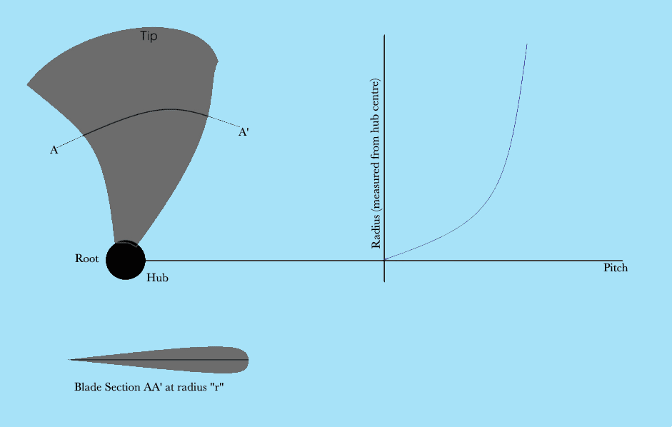
The propeller is designed in a way such that, if you cut the propeller radially at any random radius from it’s centre, then the cut section of the propeller blades will have a certain pitch (magnitude depends upon how twisted it is along the length of the hub). Now if you rotate this cut section in water, the axial distance travelled in one rotation is the pitch of this section. If you vary the radius at which you cut a section, the twist of the blade also varies from the root to the tip. This makes it evident that each section of the propeller has a particular pitch.
The root of the propeller will have a different pitch from the tip of the propeller. So the pitch variation from the root to the tip is as shown in Figure 1. The question now is, if each section has a different pitch, then what is the resultant pitch of the propeller? Answer is the resultant pitch is the average of all the pitches of each section of the propeller.
https://maritime-engineering.blogspot.com/2018/06/what-type-of-propeller-used-on-ship.htm
Blade section and variation of pitch with section
Note very carefully, that the pitch varies along with the blade section (or increasing distance from the propeller centre), but the net average or the net pitch of the propeller remains constant. Such a propeller is a fixed pitch propeller.
Now, let’s go back to the concept of a screw. What if you could somehow change the angle of inclination of the threads along the screw?
If you could, what would you actually be doing is changing the pitch angle and subsequently, the pitch of the screw.This is exactly why the controllable pitch propeller was developed by the industry. We will be dealing with the applications in detail a little later. But for now, it is vital to know the fundamental working of a Controllable Pitch Propeller (CPP) also commonly known as Variable Pitch Propeller.
The twist (to be referred as pitch from now on) of the root section of the blade is always with respect to the angle it makes with the propeller hub. What if we can change the angle of orientation of the root? And since all the other blade sections had their previous pitch angle already, they attain a new pitch angle. In other words, you are able to control the pitch of the entire propeller, by changing the orientation of the root section on the hub. This is done by the means of a hydraulic cylinder.
When the required orientation or pitch of the propeller is obtained, the blades are locked in that position. So the blades are not an integral part of (or not casted along with) the propeller hub. They are mounted on spindles that have axes perpendicular to the shaft axis.
https://maritime-engineering.blogspot.com/2018/06/what-type-of-propeller-used-on-ship.htm


Advantages and Disadvantages of CPP and FPP

The following points will discuss the applications and their relations with the advantages and disadvantages of CPP and FPP systems:
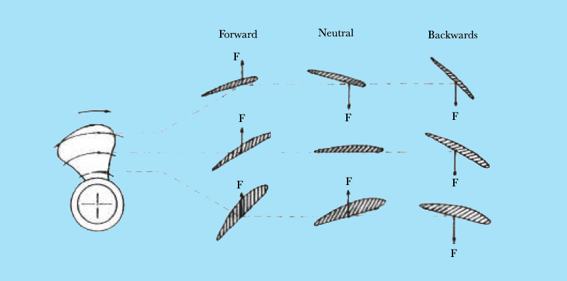
  • The controllable pitch propellers can be used to run the ship in forward and astern direction both, without the requirement to change the direction of rotation of the engine. How? Well, the propeller works on the principle of lift generated by each aerofoil section of the blade. What if we can change the orientation of the blade, such that the direction of life force is opposite to what it was during forward running of the ship? That’s exactly what is achieved by changing the pitch angle of the blades, as shown in Figure 2.
https://maritime-engineering.blogspot.com/2018/06/what-type-of-propeller-used-on-ship.htm
Blade sections shown in various pitch orientations
  • A non-reversible engine can be used for both forward and astern operation of the ship. Hence, the weight of the engine and propulsion machinery is reduced considerably when compared to what is required in propulsion systems equipped with fixed pitch propellers.
  • Since the pitch of the propeller determines the amount of thrust generated by the propeller, a change in the pitch angle can bring about a change in the speed of the ship. So, a controllable pitch propeller is useful in changing the speed of the ship without changing the speed or rpm of the main engine. But why are we focusing on this advantage? What happens if we need to reduce the engine rpm to reduce the ship’s speed? Well, many ships have a shaft driven diesel alternator system. So the rpm of the main engine shaft controls the electric power production on board. In that case, if the speed was to be reduced using a fixed pitch propeller, it would require a reduction in the shaft rpm, which would result in reduction of power generated.
  • Due to the above reason, the speed of the ship can be handled from the navigation bridge directly. In case of fixed pitch propellers, the marine engineer needs to be intimidated in order to change the ship’s speed. Therefore CPP technology is used for obtaining faster response of speed change.
  • The efficiency of astern condition in case of fixed pitch propellers is less than that of controllable pitch propeller in astern condition.
However, there are many disadvantages of using a controllable pitch propeller to a fixed pitch propeller. It is important to know them too.
  • The pitch control mechanism installed in the hub is complicated enough to demand proper inspection at regular intervals. The installation process is also more complicated as compared to that of fixed pitch propeller system.
  • Controllable pitch propellers have a very high initial cost. And this cost increases rapidly with increasing diameter of the propeller.
  • Due to pitch control mechanisms housed inside the hub, the length and the diameter of the hub is also high as compared to the fixed pitch propeller systems.
To conclude, it is vital to know the applications of controllable pitch propellers. These are used in ships that are required to operate at variable speeds even when operating at constant power requirements. Such ships are tugs, trawlers, ferries, ice breakers, and small scale warships that are equipped with gas turbines.
Procedure For Renew Propeller on ship
How to Measure Cylinder Liner Bore Wear on ship?
Types of Mechanical Measuring Tools and Gauges Used on Ships
what type of propeller used on ship? Controllable Pitch Propeller (CPP) Vs Fixed Pitch Propeller (FPP)?

Machinery onboard ships require regular care and maintenance so that their working life and efficiency can be increased, and the cost of operation, which includes unnecessary breakdowns and spares, can be reduced. For different types of machinery and systems, various measuring tools, instruments and gauges are used on a ship.
Measuring instruments and gauges are used to measure various parameters such as clearance, diameter, depth, oval... These are critical engineering parameters, which describe the condition of the working machinery.

Popular mechanical gauges and tools used on ships are:

Ruler and scales

They are used to measure lengths and other geometrical parameters. They can be a single steel plate or flexible tape type tool.

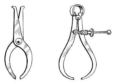
Calipers

They are usually of two types- inside and outside caliper. They are used to measure internal and external size (for e.g. diameter) of an object. It requires external scale to compare the measured value.
Some calipers are integrated with measuring scale. Other types are odd leg and divider caliper.

Vernier caliper

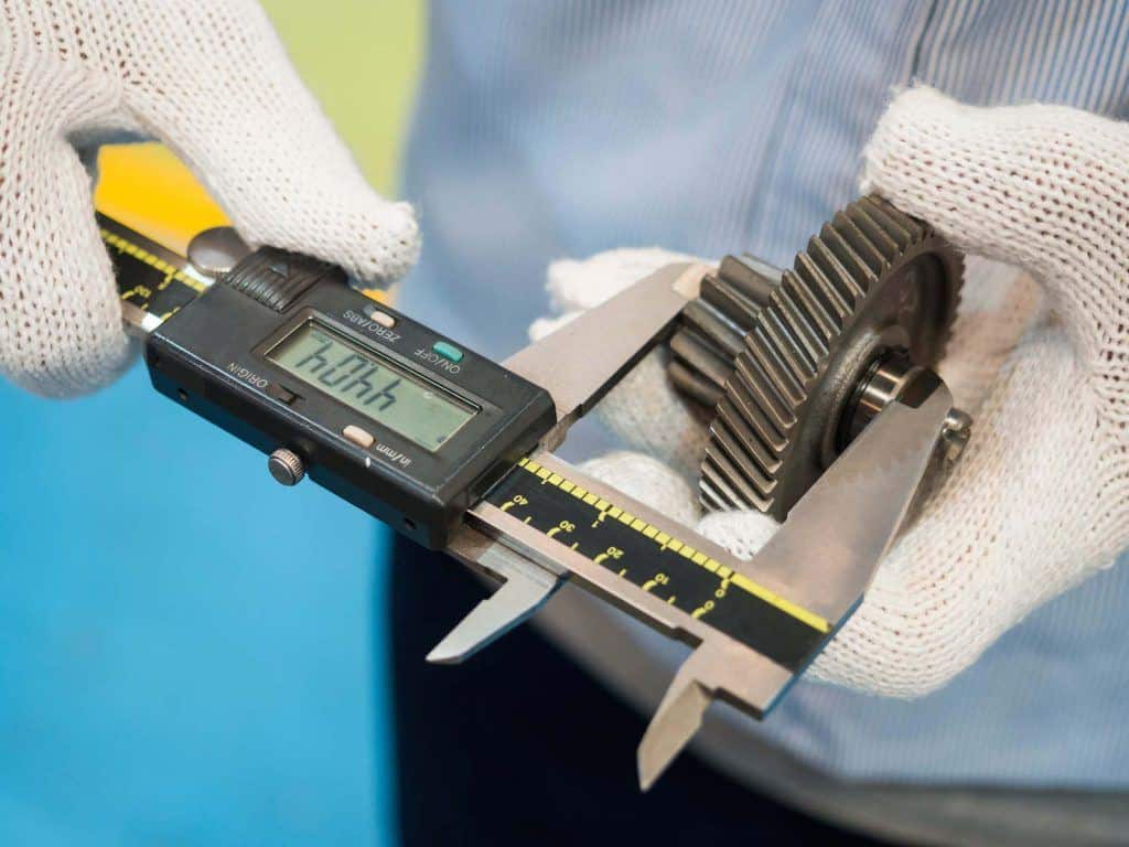
It is a precision tool used to measure a small distance with high accuracy. It has got two different jaws to measure outside and inside dimension of an object.It can be a scale, dial or digital type vernier caliper.
https://maritime-engineering.blogspot.com/2018/06/machinery-onboard-ships-require-regular.htm

Micrometer

It is an excellent precision tool which is used to measure small distances and is more accurate than the vernier caliper. Another type is a large micrometer caliper which is used to measure large outside diameter or distance.
https://maritime-engineering.blogspot.com/2018/06/machinery-onboard-ships-require-regular.htm


They are available in two types- Inside micrometer (to measure inside diameter) and Outside micrometer (for measuring outside diameter)

Feeler gauge

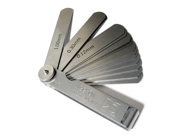
Feelers gauges are a bunch of fine thickened steel strips with a marked thickness which is used to measure gap width or clearance between surface and bearings.
https://maritime-engineering.blogspot.com/2018/06/machinery-onboard-ships-require-regular.htm

Telescopic feeler gauge

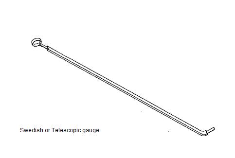
It is also known as tongue gauge, and it consists of long feeler gauge inside a cover with tongue or curved edge.

https://maritime-engineering.blogspot.com/2018/06/machinery-onboard-ships-require-regular.htm
The long feeler strips protrude out of the cover so that it can be inserted into remote places where feeler gauge access is not possible.

Poker gauge

This gauge is used to measure propeller stern shaft clearance, also known as propeller wear down

Bridge gauge

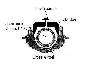
Bridge gauges are used to measure the amount of wear of Main engine bearing. Typically the upper bearing keep is removed, and clearance is measured for the journal.
Bridge Gauge
A feeler gauge or depth gauge can be used to complete the process.

Liner measurement tool

Liner measurement tool is a set of the straight assembled rod with marked length in each set. It is used to measure the wear down or increase the diameter of the engine liner.

American Wire Gauge

American wire gauge or AWG is a standard tool which is circular and has various slots of different diameter in its circumference. It is used to measure the cross section of an electric cable or wire.
Wire Gauge - AWG
Source: Wikimedia

Bore Gauge

A tool to accurately measure the size of any hole is known as bore gauge, It can be a scale, dial or digital type instrument.

https://maritime-engineering.blogspot.com/2018/06/machinery-onboard-ships-require-regular.htm

Depth gauge

A depth gauge is used to measure the depth of a slot, hole or any other surface of an object. It can be of scale, dial or digital type.

Angle plate or tool

It is a right angle plate or device used to measure the exact right angle of two objects joined together.
Angle plate

Flat plate

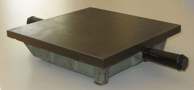
the flat plate is a precision flat surface used to measure the flatness of an object when it is kept over the flat plate.
Flat/ Surface plate

Dial Gauge

The dial gauge is utilized in different tools as stated above and can be separately used to measure the trueness of the circular object, jumping off an object, etc.
Dial Gauge
Source: Wikimedia/Solaris2006

Lead Wire

It is a conventional method to used soft lead wire or lead balls to measure the wear down or clearance between two mating surfaces. The lead wire or balls of fixed dimension are kept between two surfaces, and both are tightened against each just as in normal condition. The increase in the width of the lead wire or ball will show the clearance or wear down.

Oil Gauging tapes

Also known as sounding tapes, these are used to measure the level of the fluid (HFO, DO, Lubes, Water etc.) inside the ship’s tanks

Seawater Hydrometer

A small glass instrument for measuring the density and saturation of the salt in the seawater

Crankshaft deflection gauge

A form of dial gauge specifically made to measure the crankshaft deflection of the marine engine.
Engine peak indicator

A measuring instrument for a marine engine with pressure indicator dial used to measure the peak pressure generated inside the engine cylinder.

Engine Indicator diagram tool

It is a cylindrical device with spring and needle, used to draw the indicator diagram for a particular cylinder when it is fixed on the indicator cock of the unit.

Planimeter

An instrument which is used to measure areas of irregularly shaped areas of an arbitrary two-dimensional shape on plans or drawings.
planimeter

Thursday, June 21, 2018

https://maritime-engineering.blogspot.com/2018/06/construction-advantages-and_24.html

Introduction to valves - Ball valves

Construction - Advantages and disadvantages of Globe valves

Ball valves

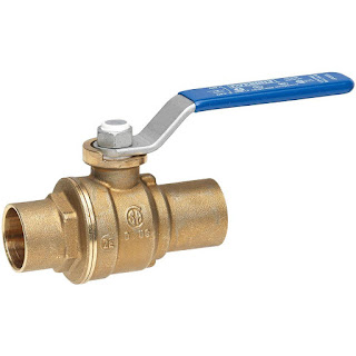
A Ball valve is a quarter-turn rotational motion valve that uses a ball-shaped disk to stop or start flow. If the valve is opened, the ball rotates to a point where the hole through the ball is in line with the valve body inlet and outlet. If the valve is closed, the ball is rotated so that the hole is perpendicular to the flow openings of the valve body and the flow is stopped.

Types of Ball valves

Ball valves are basically available in three versions: full port, venturi port and reduced port. The full-port valve has an internal diameter equal to the inner diameter of the pipe. Venturi and reduced-port versions generally are one pipe size smaller than the line size.
Ball valves are manufactured in different body configurations and the most common are:
  • Top entry Ball valves allow access to valve internals for maintenance by removal of the valve Bonnet-cover. It is not required to be removed valve from the pipe system.
  • Split body Ball valves consists of a two parts, where one part is smaller as the other. The ball is inserted in the larger body part, and the smaller body part is assembled by a bolted connection.
The valve ends are available as butt welding, socket welding, flanged, threaded and others.

Materials - Design - Bonnet

MATERIALS
Balls are usually made of several metallics, while the seats are from soft materials like Teflon®, Neoprene, and combinations of these materials. The use of soft-seat materials imparts excellent sealing ability. The disadvantage of soft-seat materials (elastomeric materials) is, that they are not can be used in high temperatures processes.
For example, fluorinated polymer seats can be used for service temperatures from −200° (and larger) to 230°C and higher, while graphite seats may be used for temperatures from ?° to 500°C and higher.
STEM DESIGN
The stem in a Ball valve is not attached to the ball. Usually it has a rectangular portion at the ball, and that fits into a slot cut into the ball. The enlargement permits rotation of the ball as the valve is opened or closed.
BALL VALVE BONNET
The Bonnet of a Ball valve is fastens to the body, which holds the stem assembly and ball in place. Adjustment of the Bonnet permits compression of the packing, which supplies the stem seal. Packing material for Ball valve stems is usually Teflon® or Teflon-filled or O-rings instead of packing.

Ball valves applications

The following are some typical applications of Ball valves:
  • Air, gaseous, and liquid applications
  • Drains and vents in liquid, gaseous, and other fluid services
  • Steam service

Advantages and disadvantages of Ball valves

ADVANTAGES:
  • Quick quarter turn on-off operation
  • Tight sealing with low torque
  • Smaller in size than most other valves
DisADVANTAGES:
  • Conventional Ball valves have poor throttling properties
  • In slurry or other applications, the suspended particles can settle and become trapped in body cavities causing wear, leakage, or valve failure.

Construction - Advantages and disadvantages of Globe valves

Globe valves

A Globe valves is a linear motion valve and are primarily designed to stop, start and regulate flow. The disk of a Globe valve can be totally removed from the flowpath or it can completely close the flowpath.
Conventional Globe valves may be used for isolation and throttling services. Although these valves exhibit slightly higher pressure drops than straight=through valves (e.g., gate, plug, ball, etc.), they may be used where the pressure drop through the valve is not a controlling factor.
Because the entire system pressure exerted on the disc is transferred to the valve stem, the practical size limit for these valves is NPS 12 (DN 300). Globe valves larger than NPS 12 (DN 300) are an exception rather than the rule. Larger valves would require that enormous forces be exerted on the stem to open or close the valve under pressure. Globe valves in sizes up to NPS 48 (DN 1200) have been manufactured and used.
Globe valves are extensively employed to control flow. The range of flow control, pressure drop, and duty must be considered in the design of the valve to avert premature failure and to assure satisfactory service. Valves subjected to high-differential pressure-throttling service require specially designed valve trim.
Generally the maximum differential pressure across the valve disc should not exceed 20 percent of the maximum upstream pressure or 200 psi (1380 kPa), whichever is less. Valves with special trim may be designed for applications exceeding these differential pressure limits.
Body designs of Globe valves
There are three primary body designs for Globe valves, namely: Tee Pattern or Z-body, Angle Pattern and Wye Pattern or Y-body body.
TEE PATTERN GLOBE VALVE DESIGN is the most common body type, with a Z-shaped diaphragm. The horizontal setting of the seat allows the stem and disk to travel perpendicular to the horizontal line. This design has the lowest coefficient of flow and higher pressure drop. They are used in severe throttling services, such as in bypass lines around a control valve. Tee-pattern Globe valves may also be used in applications where pressure drop is not a concern and throttling is required.

Tee Pattern or Z-shaped Globe valve


ANGLE PATTERN GLOBE VALVES DESIGN is a modification of the basic Tee Pattern Globe valve. The ends of this Globe valve are at an angle of 90 degrees, and fluid flow occurs with a single 90 degrees turn. They have a slightly lower coefficient of flow than wye-pattern Globe valves. They are used in applications that have periods of pulsating flow because of their capability to handle the slugging effect of this type of flow.

Angle-body Globe valve


WYE PATTERN GLOBE VALVES DESIGN, is an alternative for the high pressure drop, inherent in Globe valves. Seat and stem are angled at approximately 45 degrees, what gives a straighter flowpath at full opening and offer the least resistance to flow. They can be cracked open for long periods without severe erosion. They are extensively used for throttling during seasonal or startup operations. They can be rod through to remove debris when used in drain lines that are normally closed.

Y-body Globe valve


Disk & Seat & Stem of Globe valves

DISK: The most common disk designs for Globe valves are: ball disk, composition disk and the plug disk. Ball disk design is used primarily in low pressure and low temperature systems. It is capable of throttling flow, but in principle it is applied to stop and start flow.
Composition disk design uses a hard, non-metallic insert ring on the disk, which ensures a tighter closure.
Plug disk design provides better throttling than ball or composition designs. They are available in many different designs and they are all long and tapered.
SEAT: Globe valve seats are either integrated or screwed in to the valve body. Many Globe valves have backseats inside the Bonnet. Back seats provides a seal between the stem and Bonnet and prevents system pressure from building against the valve pakking, when the valve is fully open. Back seats are often applied in Globe valves.
STEM: Globe valves uses two methods for connecting the disk and the stem: the T-slot and the disk nut construction. In the T-slot design, the disk slides over the stem, while in the disk nut design, the disk is screwed into the stem.
Globe valve
https://maritime-engineering.blogspot.com/2018/06/construction-advantages-and_21.html

Construction of a Globe valve

Globe valves usually have rising stems, and the larger sizes are of the outside screw-and-yoke construction. Components of the Globe valve are similar to those of the gate valve. This type of valve has seats in a plane parallel or inclined to the line of flow.
Maintenance of Globe valves is relatively easy, as the discs and seats are readily refurbished or replaced. This makes Globe valves particularly suitable for services which require frequent valve maintenance. Where valves are operated manually, the shorter disc travel offers advantages in saving operator time, especially if the valves are adjusted frequently.
The principal variation in Globe-valve design is in the types of discs employed. Plug-type discs have a long, tapered configuration with a wide bearing surface. This type of seat provides maximum resistance to the erosive action of the fluid stream. In the composition disc, the disc has a flat face that is pressed against the seat opening like a cap. This type of seat arrangement is not as suitable for high differential pressure throttling.
In cast-iron Globe valves, disc and seat rings are usually made of bronze. In steel-Globe valves for temperature up to 750°F (399°C), the trim is generally made of stainless steel and so provides resistance to seizing and galling. The mating faces are normally heat-treated to obtain differential hardness values. Other trim materials, including cobalt-based alloys, are also used.
The seating surface is ground to ensure full-bearing surface contact when the valve is closed. For lower pressure classes, alignment is maintained by a long disc locknut. For higher pressures, disc guides are cast into the valve body. The disc turns freely on the stem to prevent galling of the disc face and seat ring. The stem bears against a hardened thrust plate, eliminating galling of the stem and disc at the point of contact.

Flow direction of Globe valves

For applications with low temperature, Globe valves are normally installed so that the pressure is under the disc. This contributes an easy operation and helps protect the packing.
For applications with high temperature steam service, Globe valves are installed so that the pressure is above the disk. Otherwise, the stem will contract upon cooling and tend to lift the disk off the seat.

Advantages and disadvantages of Globe valves

ADVANTAGES:
  • Good shutoff capability
  • Moderate to good throttling capability
  • Shorter stroke (compared to a gate valve)
  • Available in tee, wye, and angle patterns, each offering unique capabilities
  • Easy to machine or resurface the seats
  • With disc not attached to the stem, valve can be used as a stop-check valve
DISADVANTAGES:
  • Higher pressure drop (compared to a gate valve)
  • Requires greater force or a larger actuator to seat the valve (with pressure under the seat)
  • Throttling flow under the seat and shutoff flow over the seat

Typical Applications of Globe valves

The following are some of the typical applications of Globe valves:
  • Cooling water systems where flow needs to be regulated
  • Fuel oil system where flow is regulated and leaktightness is of importance
  • High-point vents and low-point drains when leaktightness and safety are major considerations
  • Feedwater, chemical feed, condenser air extraction, and extraction drain systems
  • Boiler vents and drains, main steam vents and drains, and heater drains
  • Turbine seals and drains
  • Turbine lube oil system and others
https://maritime-engineering.blogspot.com/2018/06/construction-advantages-and.html

Construction - Advantages and disadvantages of Globe valves

Gate valves

Gate valves are primarily designed to start or stop flow, and when a straight-line flow of fluid and minimum flow restriction are needed. In service, these valves generally are either fully open or fully closed.
The disk of a Gate valve is completely removed when the valve is fully open; the disk is fully drawn up into the valve Bonnet. This leaves an opening for flow through the valve at the same inside diameter as the pipe system in which the valve is installed. A Gate valve can be used for a wide range of liquids and provides a tight seal when closed.

Construction of a Gate valve

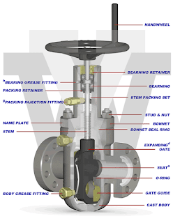
Gate valves consists of three main parts: body, bonnet, and trim. The body is generally connected to other equipment by means of flanged, screwed or welded connections. The bonnet, which containing the moving parts, is attached to the body, usually with bolts, to permit maintenance. The valve trim consists of the stem, the gate, the disc or wedge and the seat rings.

Disks of a Gate valve

Gate valves are available with different disks or wedges. Ranging of the Gate valves is usually made by the type of wedge used.
The most common were:
  • Solid wedge is the most commonly used disk by its simplicity and strength.
    A valve with this type of wedge can be installed in each position and it is suitable for almost all liquids. The solid wedge is a single-piece solid construction, and is practically for turbulent flow.
  • Flexible wedge is a one-piece disc with a cut around the perimeter to improve the ability to correct mistakes or changes in the angle between the seats.
    The reduction will vary in size, shape and depth. A shallow, narrow cut gives little flexibility but retains strength.
    A deeper and wider cut, or cast-in recess, leaves little material in the middle, which allows more flexibility, but compromises strength.
  • Split wedge is self-adjusting and selfaligning to both seats sides. This wedge type consists of two-piece construction which seats between the tapered seats in the valve body. This type of wedge is suitable for the treatment of non-condensing gases and liquids at normal temperatures, particularly corrosive liquids
  • Stem of a Gate valve

    The stem, which connects the handwheel and disk with each other, is responsible for the proper positioning of the disk. Stems are usually forged, and connected to the disk by threaded or other techniques. To prevent leakage, in the area of the seal, a fine surface finish of the stem is necessary.
    Gate valves are classified as either:
    • Rising Stem
    • Non Rising Stem
    For a valve of the Rising Stem type, the stem will rise above the handwheel if the valve is opened. This happens, because the stem is threaded and mated with the bushing threads of a Yoke. A Yoke is an integral part from a Rising Stem valve and is mounted to the Bonnet.
    For a valve of the non Rising Stem type, there is no upward stem movement if the valve is opened. The stem is threaded into the disk. As the handwheel on the stem is rotated, the disk travels up or down the stem on the threads while the stem remains vertically stationary.
  • Seats of a Gate valve

    Seats for Gate valves are either provided integral with the valve body or in a seat ring type of construction. Seat ring construction provides seats which are either threaded into position or are pressed into position and seal welded to the valve body. The latter form of construction is recommended for higher temperature service.
    Integral seats provide a seat of the same material of construction as the valve body while the pressed-in or threaded-in seats permit variation. Rings with hard facings may be supplied for the application where they are required.

    Advantages and disadvantages of Gate valves

    ADVANTAGES:
    • Good shutoff features
    • Gate valves are bidirectional and therefore they can be used in two directions
    • Pressure loss through the valve is minimal
    DIAADVANTAGES:
    • They can not be quickly opened or closed
    • Gate valves are not suitable for regulate or throttle flow
    • They are sensitive to vibration in the open state
https://maritime-engineering.blogspot.com/2018/06/installation-procedures-butterfly-valves.html

Construction - Advantages and disadvantages of Globe valves

Construction - Advantages and disadvantages of Gate valves

Avoiding problems with Butterfly valves

The majority of all problems with Butterfly valves in the field are directly related to poor installation procedures. For this reason, it is wise to consider best-practice when laying out pipe-work and installing the valve itself.
The seat in a resilient-seated Butterfly valve usually extends around to both faces of the valve. As a result, no gaskets are required as these seats serve the function of a gasket. The seat material which extends past the face is compressed during installation and flows toward the center of the valve seat. Any change in this configuration due to improper installation directly affects the pressure rating and seating/unseating torques.
Unlike most valve types, the Butterfly valve's disc actually extends beyond the face of the valve body at given angles of opening (say, 30° or more) when installed between flanges. Therefore, it is very important before installation to ensure that the disc is able to freely turn and enter the flanges and pipe-work.

Shipment & Storage

  • Position discs at 10% open so that they are unseated.
  • The faces of each valve should be covered to prevent damage to the seat face, disc edge, or valve interior.
  • Store indoors, preferably with ambient temperatures between 5°C and 30°C.
  • Open and close the valves every 3 months.
  • Ship and store valves so that no heavy loads are applied to the bodies.

Valve Location

  • Butterfly valves should be installed if possible a minimum of 6 pipe diameters from other line elements, i.e. elbows, pumps, valves, etc. Sometimes this is not feasible, but it is important to achieve as much distance as possible.
  • Where the Butterfly valve is connected to a check valve or pump, keep enough space between them to ensure the disc does not interfere with the adjacent equipment.

Valve Orientation

As a rule of thumb, Butterfly valves be installed with the stem in the vertical position with the actuator mounted vertically directly above it, however, there are some applications where the stem should be horizontal. 

Advantages of Butterfly valves
  • Compact design requires considerably less space, compared to other valves
  • Light in weight
  • Quick operation requires less time to open or close
  • Available in very large sizes
  • Low-pressure drop and high-pressure recovery
Disadvantages of Butterfly valves
  • Throttling service is limited to low differential pressure
  • Cavitation and choked flow are two potential concerns
  • Disc movement is unguided and affected by flow turbulence

Butterfly valves

Construction - Advantages and disadvantages of Globe valves


A Butterfly valve is a quarter-turn rotational motion valve, that is used to stop, regulate, and start flow.
Butterfly valves are easy and fast to open. A 90° rotation of the handle provides a complete closure or opening of the valve. Large Butterfly valves are usually equipped with a so-called gearbox, where the hand wheel by gears is connected to the stem. This simplifies the operation of the valve, but at the expense of speed.

Types of Butterfly valves

Butterfly valves has a short circular body, a round disc, metal-to-metal or soft seats, top and bottom shaft bearings, and a stuffing box. The construction of a Butterfly valve body varies. A commonly used design is the wafer type that fits between two flanges. Another type, the lug wafer design, is held in place between two flanges by bolts that join the two flanges and pass through holes in the valve's outer casing. Butterfly valves are even available with flanged, threaded and butt welding ends, but they are not often applied.
Butterfly valves possess many advantages over gate, globe, plug, and ball valves, especially for large valve applications. Savings in weight, space, and cost are the most obvious advantages. The maintenance costs are usually low because there are a minimal number of moving parts and there are no pockets to trap fluids.
Butterfly valves are especially well-suited for the handling of large flows of liquids or gases atrelatively low pressures and for the handling of slurries or liquids with large amounts ofsuspended solids.
Butterfly valves are built on the principle of a pipe damper. The flow control element is a disk of approximately the same diameter as the inside diameter of the adjoining pipe, which rotates on either a vertical or horizontal axis. When the disk lies parallel to the piping run, the valve is fully opened. When the disk approaches the perpendicular position, the valve is shut. Intermediate positions, for throttling purposes, can be secured in place by handle-locking devices.

Butterfly valve Seat Construction

Stoppage of flow is accomplished by the valve disk sealing against a seat that is on the inside diameter periphery of the valve body. Many Butterfly valves have an elastomeric seat against which the disk seals. Other Butterfly valves have a seal ring arrangement that uses a clamp-ring and backing-ring on a serrated edged rubber ring. This design prevents extrusion of the O-rings.
In early designs, a metal disk was used to seal against a metal seat. This arrangement did not provide a leak-tight closure, but did provide sufficient closure in some applications (i.e., water distribution lines).

Butterfly valve Body Construction

Butterfly valve body construction varies. The most economical is the wafer type that fits between two pipeline flanges. Another type, the lug wafer design, is held in place between two pipe flanges by bolts that join the two flanges and pass through holes in the valve's outer casing. Butterfly valves are available with conventional flanged ends for bolting to pipe flanges, and in a threaded end construction.

Seat Disk and Stem of a Butterfly valve

The stem and disk for a Butterfly valve are separate pieces. The disk is bored to receive the stem. Two methods are used to secure the disk to the stem so that the disk rotates as the stem is turned. In the first method, the disk is bored through and secured to the stem with bolts or pins. The alternate method involves boring the disk as before, then shaping the upper stem bore to fit a squared or hex-shaped stem. This method allows the disk to "float" and seek its center in the seat. Uniform sealing is accomplished and external stem fasteners are eliminated. This method of assembly is advantageous in the case of covered disks and in corrosive applications.
In order for the disk to be held in the proper position, the stem must extend beyond the bottom of the disk and fit into a bushing in the bottom of the valve body. One or two similar bushings are along the upper portion of the stem as well. These bushings must be either resistant to the media being handled or sealed so that the corrosive media cannot come into contact with them.
Stem seals are accomplished either with packing in a conventional stuffing box or by means of O-ring seals. Some valve manufacturers, particularly those specializing in the handling of corrosive materials, place a stem seal on the inside of the valve so that no material being handled by the valve can come into contact with the valve stem. If a stuffing box or external O-ring is employed, the fluid passing through the valve will come into contact with the valve stem.

Typical applications of Butterfly valves

A Butterfly valve can be used in many different fluid services and they perform well in slurry applications. The following are some typical applications of Butterfly valves:
  • Cooling water, air, gases, fire protection etc.
  • Slurry and similar services
  • Vacuum service
  • High-pressure and high-temperature water and steam services