Showing posts with label MAINTENANCE. Show all posts

Saturday, June 23, 2018


Propeller is the most significant machinery system of the ship. No matter what type of propeller it is, ship owners never make compromises on such important equipment as it directly affects the efficiency and safety of the vessel. Here we discuss about fixed pitch keyless propeller renewal.

Why is propeller renewed?

There are various reasons for which a ship’s propeller could be renewed. Some of the significant reasons are:
1) Damage to the propeller
2) Dynamically unbalanced
3) Renewing the existing propeller with a new propeller that is of better material, larger blade area etc.
https://maritime-engineering.blogspot.com/2018/06/procedure-for-renew-propeller-on-ship.html
Below we will learn about the procedures involved in renewing a propeller.
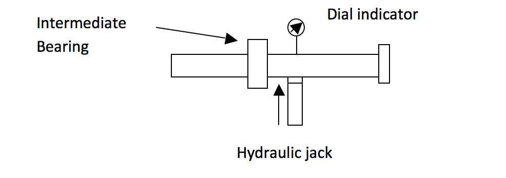
Before decoupling the intermediate shaft and the propeller shaft (tail shaft), make thorough inspection of the propulsion system. Generally, the shaft jack up test is done before removing the intermediate shaft.
https://maritime-engineering.blogspot.com/2018/06/procedure-for-renew-propeller-on-ship.html
Fig 1. Jack up test arrangement
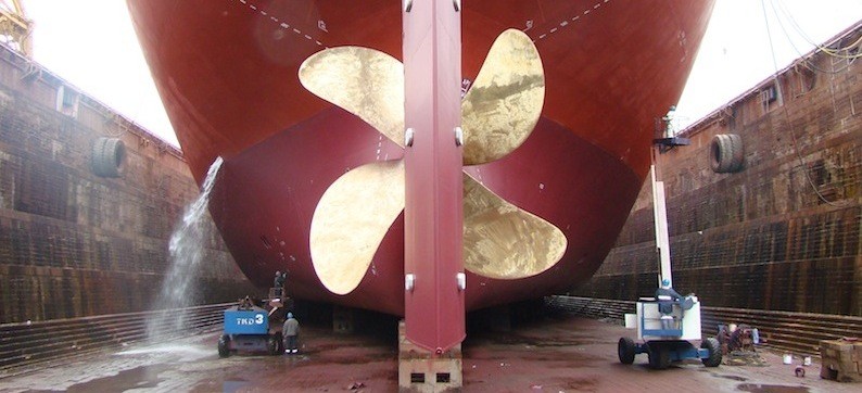
ship propeller
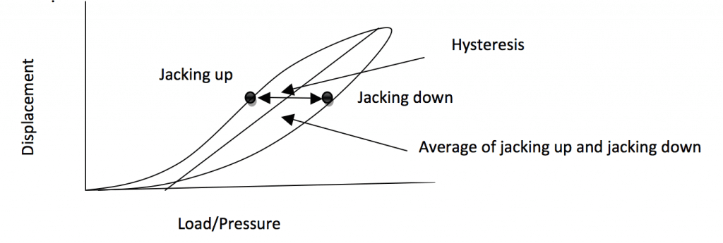
Figure 2: Displacement VS. Load
Important points on Jack up test:
1) In jack up test we actually jack up the shaft to get vivid picture of the bearing reaction, the results need to be corrected
2) Hence, it is advised to place the hydraulic jack close to the bearing for better accuracy
3) To verify the results, ABS reaction Coefficient matrix can be referred wherein the expected gradient of the average line in the curve is tabulated (see the above figure).
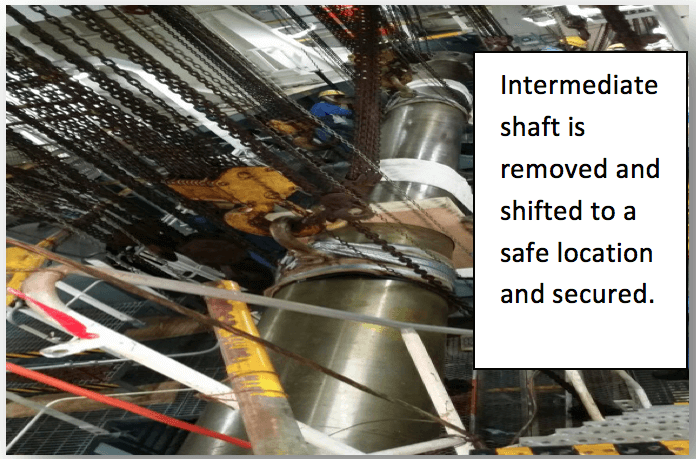
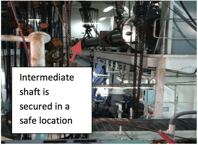
Once the Jack up test is done, Intermediate bearing cap is removed, and then the intermediate shaft is removed prior to which the tail shaft is secured. It is very important to protect the bearing area. Necessary pad eyes need to be welded, make sure redundant pad eyes are welded and lifting arrangements are sufficient to take the load of the intermediate shaft. Another important thing to note is the location where the intermediate shaft can be secured.
https://maritime-engineering.blogspot.com/2018/06/procedure-for-renew-propeller-on-ship.html
Figure 3: Intermediate shaft removal
ship propeller change
Figure 4: Intermediate shaft removal
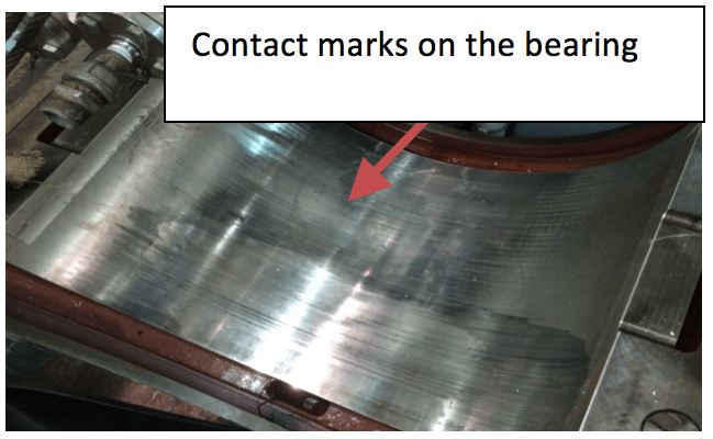
Once the intermediate shaft is removed and secured in a safe location in the ship, check the condition of the plumber block bearings. Look for any white metal debris or contact marks.
https://maritime-engineering.blogspot.com/2018/06/procedure-for-renew-propeller-on-ship.html
Image 5: Intermediate shaft bearing
The tail shaft removal is done in the dry dock.
– For this, the first step is to cut the rope guard and keep it aside. Propeller cone is to be removed and then slack the aft stern tube seal (prior to which stern tube oil need to be drained).
– Then propeller nut is removed (make sure reference point is marked on the tail shaft) and the propeller is secured prior to the tail shaft removal.
– Lifting and shifting arrangements need to be pre-planned.
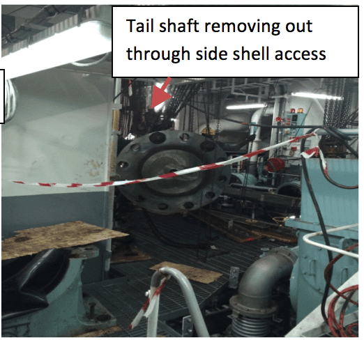
– Remove the forward stern tube seal and then pull the tail shaft and shift to the lifting zone; in some cases tail shaft can be removed through the skylight but in most cases it requires cutting ship side shell for access. Tail shaft is carefully pulled out through the stern tube and removed through the access. It is advised to perform NDT on the tail shaft taper area.
https://maritime-engineering.blogspot.com/2018/06/procedure-for-renew-propeller-on-ship.html
Figure 7: Tail shaft removal

Propeller –Tail Shaft Bedding

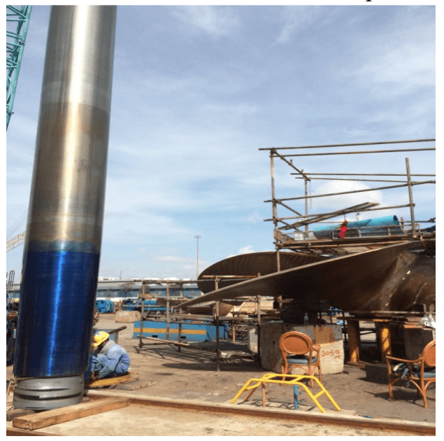
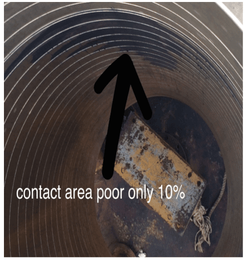
Propeller and tail shaft bedding reveals how good is the contact. This is done by applying Prussian blue to the tail shaft tapered area. The tail shaft is then lifted vertically and matted to the propeller hub which is positioned horizontally. The contact area in the hub is visually examined and the class requires at least 70-80% of contact. Blue mark zone on the hub is polished and process is repeated until you get 70-80% fit.
Propeller –tail shaft bedding
Figure 8: Propeller –tail shaft bedding
prop9
Figure 9: Propeller –tail shaft bedding

Propeller Mounting

On completion and satisfaction of propeller bedding, tail shaft and other accessories that are removed are installed back. Then the propeller is mounted. This is a significant stage and careful attention is paid during the same. Here we will discuss about the oil injection method for a keyless propeller mounting.
1) Clean the propeller boss and the propeller shaft
2) Slide the propeller to the propeller shaft and align to the match marks. (Prior to this step, remember to record the temperature of propeller boss and propeller shaft)
3) Screw in the Pilgrim Nut
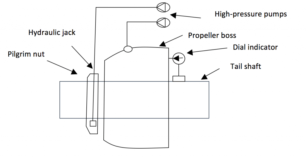
4) Dry fit: Actuate the high-pressure pump connecting the Pilgrim nut, allow the propeller to slide in to certain distance and set the dial indicator to zero. The maker always recommends initial load
5)Wet fit: Then actuate the high pressure pump connecting the propeller boss expansion oil port and simultaneously actuate the nut pressure pump. Raise the pressure gradually until the predetermined push up length is achieved (determination of push up length is explained below)
6) Once the required push up length is achieved gradually release the pressure of boss expansion port and then release the nut pressure
7) Remove all the connections and plug both propeller boss port and pilgrim nut port
8) Remember to take shaft jack up test post the installation
9) Verify the coupling alignment using sag and gap method
Propeller mounting arrangement
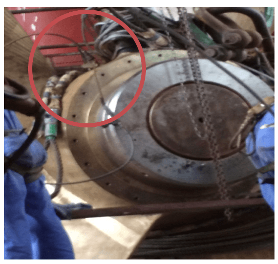
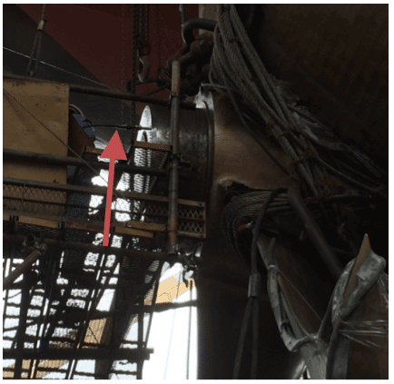
propeller push up arrangement
Figure 10: Propeller push up arrangement
propeller push up arrangement
Figure 11: Propeller push up arrangement
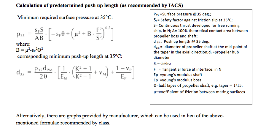
Calculation of predetermined push up length (as recommended by IACS)

calculation
Alternatively, there are graphs provided by manufacturer, which can be used in lieu of the above-mentioned formulae recommended by the class.
Permissible push up length can be captured for the corresponding temperature.

Conclusion

Propeller renewal is not about removing the existing propeller and just installing the new one, there are many other significant factors to overcome. Following are important points to be taken care of:
1) Good interference fit to transmit the torque: Damaging factor here is the varying temperature and differential thermal expansion of the propeller hub (bronze) and propeller shaft (steel).
Thermal expansion coefficient of bronze is about 10 and steel is about 7 (in 10-6 in/Fahrenheit). This will affect the fitting, hence keeping all this in mind required push up length is calculated such that the sufficient friction is achieved to transmit the torque.
torque

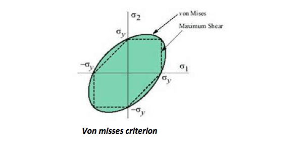
2) Reduced stress on propeller hub and propeller shaft: Von misses stress should be less than 0.7 times yield stress of propeller material. Von misses criterion is one of the most commonly used failure theory.
To assess the von misses stress:
1) Derive the stress elements
2) Find the principal stresses (Mohr’s circle)
circle
 3) From the principal stresses von misses stress can be derived (for 2d). If it is greater than the yield strength, then the material fails. It is just a simple explanation about von misses stress. Taking all these into account, maker represent the minimum push up length graphically.
https://maritime-engineering.blogspot.com/2018/06/all-types-of-ship-machines-and-parts.html

Construction - Advantages and disadvantages of Globe valves


All types of ship machines and parts get worn out due to continuous usage and working. Proper maintenance and routine checks are necessary to ensure that the machines work for a longer time. In this article, we will have a look at various reasons that lead to cylinder liner wear and how it can be minimised.

Reasons for Cylinder Liner Wear

The wear in the cylinder liner is mainly because of following reasons:
1) Due to friction.
2) Due to corrosion.
3) Abrasion
4) Scuffing or Adhesion

Frictional Wear:

Whenever two surfaces slide over each other, friction is produced which leads to wearing down of both the surfaces. In liner wear, the surfaces are piston rings sliding over the cylinder liner. The frictional wear depends upon various factors like speed of movement between the surfaces, material involved, temperature, the load on engine, pressure, maintenance, lubrication, and combustion efficiency.

Corrosion:

The cylinder liner wear due to corrosion is caused due to these reasons:
– Burning of heavy fuel oil in the combustion space:
This happens because heavy fuel oil contains high sulfur content. During combustion, acids are formed inside the space which should be neutralised by cylinder oil which is alkaline in nature. The production of acids will be more if sulfur content is more, leading to the formation of sulphuric acid. Sulphuric acid is formed due to absorption of the condensate or moisture present inside the combustion space.
– Lower combustion chamber temperature because of reduced service load:
As the low load operation of the marine engine is gaining popularity, it also leads to low temperature in the combustion chamber. If the cylinder oil quantity is not matched properly with the load, it may lead to corrosion of liner.
Acid sulfuric corrosion is found more in the lower part of the liner as the temperature of jacket water is very low. Corrosion due to sulfur will be high due to the presence of water in fuel and condensate in the air. This wear is generally seen between the quills. The wear near the quills enlarges and gives a characteristic of the clover leaf shape to the wear pattern. This phenomenon is called clover leafing.

Abrasion

This type of cylinder liner wear is due to the hard particles present and formed during combustion. Catalytic fines in the fuel, the ash formed during the combustion, metal swarf, dust and accumulated wear particles in the lube oil cause abrasive wear.
The abrasion wear rate is higher at TDC and BDC of the liner. Once the abrasive wear hits the surface, due to exposure of metal without protection, it is highly susceptible to corrosion wear too.

Adhesion or Scuffing

This is a form of local welding between the particles of piston rings and the liner surface. As the piston is moving inside the liner, the welding which has occurred breaks and leads to the formation of abrasive material. The abrasive material will increase the rate of wear of the liner. This is generally caused by insufficient lubrication due to which a large amount of heat is produced and microscopic welding of rings and liner surface takes place. Due to this type of wear the liner loses its properties to adhere cylinder oil to the surface. One more reason or this phenomenon is polishing of the surface caused by scuffing, giving liners a mirror finish.

How Can Cylinder Liner Wear be Minimised?

Cylinder wear can be minimised by carrying out the following steps:
1) By avoiding any ingress of water inside the liner by properly treating the fuel oil.
2) By maintaining the correct grade of cylinder oil.
3) By supplying correct feed rate with load change dependent lubrication system
4) By avoiding ingress of moisture from the charge air.
5) By maintaining proper jacket water temperature.
6) By supplying good quality purified fuel oil inside the combustion chamber
7) By properly maintaining the fuel injector and fuel system for correct atomization and injection of fuel inside the chamber
8) By doing regular scavenge port inspection for early detection of piston ring wear and liner surface wear
9) By doing proper running in of new liner as prescribed by the engine maker
10) By honing the wear liner surface to retain oil in the small pocket avoiding scuffing and other problems

How to Measure Cylinder Liner Bore Wear?

Cylinder liner ovality has to be gauged at regular intervals as specified in the maintenance manual. The records of gauging are kept for each cylinder and wear rate is calculated.
https://maritime-engineering.blogspot.com/2018/06/how-to-measure-cylinder-liner-bore-wear.html

Procedure:

1. After engine is shut down and cooled, open the cylinder head and remove the piston
2. Cover the stuffing box hole to avoid debris falling inside crankcase
3. Remove the liner ring and clean the carbon deposits from top surface of the liner
4. Insert a ladder and carefully inspect the liner surface before gauging
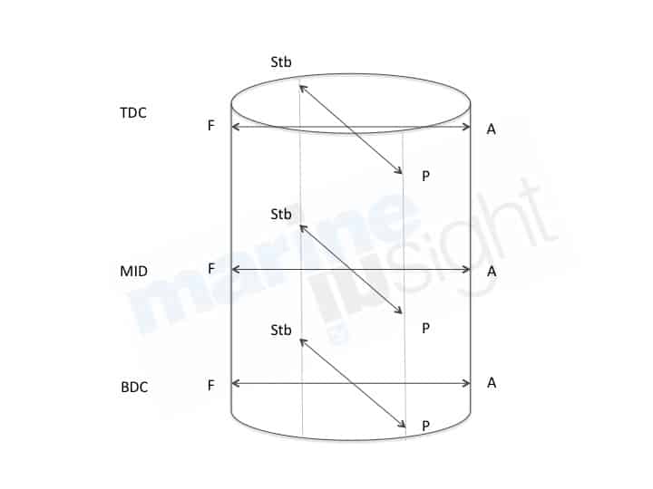
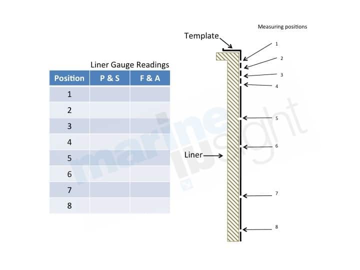
5. The cylinder liner wear is measured by a standard template, which consists of strategically positioned holes, wherein the micrometer is placed and the readings are taken
6. The readings are taken for both port starboard and forward aft positions. This is done because the wear is not same in both direction and the cylinder liner ovality is checked.
A liner diameter measuring instrument ( a type of micrometer) along with a standard template rod is used to measure liner dimensions. Generally while taking the measurement the temperature of the liner and micrometer should be kept at the same temperature.
If the temperature exceeds than that of the liner or vice versa then the readings have to be corrected by multiplying the value with the correction factor and deducting the value obtained from the reading taken. The reading obtained at the end will be the correct reading.
https://maritime-engineering.blogspot.com/2018/06/how-to-measure-cylinder-liner-bore-wear.html
The wear rate will be different inside the liner. The wear will be more in the top one-third part as combustion takes place there and temperatures and pressure are also very high at the top.

How to Calculate Cylinder Liner Wear Rate and Ovality?

For calculating the cylinder liner wear rate, the current reading is compared with the last taken reading. Suppose, for a liner of 800 mm bore, the position 1 latest reading (for P-S) comes out to be 841.81. The last recorded reading for position 1 (P-S) is 841.45. Hence the wear for this position in P-S direction is 0.36.
Now the position 1 latest reading (for F-A) comes out to be 841.78. The last recorded reading for position 1 (F-A) is 841.45. Hence the wear for this position in F-A direction is 0.33.
To calculate the ovality, the F-A wear rate is deducted from P-S wear rate, which will be 0.03.
Similarly, cylinder liner wear rate and cylinder liner ovality for all positions are calculated in a similar manner.
An approximate normal cylinder liner wear rate is about 0.1 mm per 1000 running hours. The wear rate increases if the engine is overloaded. Generally, the liner has to be replaced when the cylinder liner wear rate is about 0.6-0.8% of the bore diameter or as per the manufacturer’s recommendation

Thursday, June 21, 2018

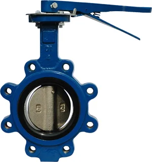
https://maritime-engineering.blogspot.com/2018/06/installation-procedures-butterfly-valves.html

Construction - Advantages and disadvantages of Globe valves

Installation Procedures

  1. Make sure the pipeline and flange faces are clean. Any foreign material such as metal filings, pipe scale, welding slag, welding rods, etc. can limit disc movement or damage the disc or seat.
  2. Gaskets are not required on resilient seated valves because they extend to both faces of the valve.
  3. Align the pipe-work, and spread the flanges enough to allow the valve body to be easily inserted between the flanges without contacting the pipe flanges.
  4. Check that the valve disc has been set to about 10% open so it doesn't become jammed in the fully seated position.
  5. Insert the valve between the flanges as shown, taking care not to damage the seat faces. Always lift the valve by the locating holes or by using a nylon sling on the neck or the body. Never lift the valve by the actuator or operator mounted on the valve.
  6. Place the valve between the flanges, centre it, insert the bolts and hand-tighten them. Carefully open the disc, making sure the disc does not contact the inside of the adjacent pipes.
  7. Very slowly close the valve disc to ensure disc edge clearance from the adjacent pipe flange.
  8. Fully open the disc and tighten all flange bolts as shown.
  9. Repeat a full close to full open rotation of the disc to ensure proper clearances.

Wednesday, June 20, 2018

Advantages of screw pumps:

+ Slow Speed, Simple and Rugged design

Probably the main and overall advantage of a screw pump is its superb reliability. The simple design, open structure and slow rotation speed makes it a heavy duty pump with minimal wear that operates for years without trouble.

+ Pumps raw water with heavy solids and floating debris

Because of the open structure and large passage between the flights a screw pump can pump raw sewage without the need for a coarse screen before the pump. Both floating debris and heavy solids are simply lifted up. This saves considerably on equipment costs for a coarse screen or maintenance!

+ Can run without water

A screw pump can operate even when there is no water in the inlet. Therefore it is not necessary to install expensive measures (level control etc) to prevent ‘dry-running’’. The lower bearing does not need cooling.

+ No collection sump required = minimum head

A screw pump ‘scoops’ the water directly from the surface and does not need a collection sump. This keeps the pump head to a minimum.

+ Constant high efficiency with variable capacity

The efficiency-curve of a screw pump is flat on the top. Due to that efficiency characteristic, the screw pump offers even high efficiency when it works at 50% of its capacity.

+ Pump capacity is self-regulating with incoming level

When incoming water-level goes down, at dry weather flow, the screw pump ‘automatically’ pumps less water. Ergo: no control system required to adapt pump performance.

+ 'Gentle handling' of biological flock

The activated return sludge on STP’s is a delicate biological substance. Because of the low rotational speed and large opening between the flights, screw pumps do not damage this biological flock (whereas the high speed rotating centrifugal pumps will completely shred the biological flock).

+ Easy maintenance (no 'high skilled' staff required)

A screw pump requires very little maintenance. Compared to (submersed) centrifugal pumps it is next to nothing. Besides that no ‘highly skilled’ maintenance staff are required which makes this type of pump very suitable for remote locations.

+Long lifetime ( > 20-40 years)

Screw pumps with typical lifetimes of between 20-40 years are not unusual.

Disadvantages of Propeller / Centrifugal Pumps:

- High speed = increased wear

The relatively high operational speed (450 – 950 rpm) causes wear and damage in the pump housing, this is particularly so when pumping waste water containing sand and stones. This wear results in regular expensive repairs to the housings.

-Possible blockages at reduced capacities

At reduced capacities the speed in the vertical pipe reduces to such an extent that the solids fall out of suspension to the bottom of the pipe causing blockages which eventually stop the pump.

- Heavy solids cannot be pumped

Heavy solids cannot be pumped; the sump eventually fills with the solids which have to be removed by hand by maintenance staff. Alternatively a coarse screen would need to be installed which increases the total equipment costs!

- Floating debris is not pumped

Floating debris is not removed; this collects in the sump and has to be removed by hand. Moreover, at lower water levels in the sump when the spirals of the pump are not completely covered, floating (wooden) debris can enter the conical spiral causing the pump to block. Repair is difficult necessitating complete dismantling of the pump.

- Dry running is fatal

A centrifugal pump will be severely damaged when running dry; it is therefore necessary to install expensive measures (level control etc) to prevent ‘dry-running’.

- High friction losses in pipes

High speed is required in the vertical discharge pipe in order to lift the solids with the waste water, obtaining this high speed requires the use of small diameter piping. Using small diameter piping causes high friction losses in the pipe which increases energy consumption.

- Mechanical seals need regular adjustment

The mechanical seal between the pump and motor requires regular adjustment or replacement which is time consuming (isolation and wash down required) and hence expensive.

- Lifting facilities required with each maintenance

Even low capacity pumps (100 l/s) are too heavy to lift by hand, therefore every time repair is required a mobile crane must be used or permanent lifting facilities must be installed – either option being expensive.

- Higher skilled maintenance staff required

The submerged pumps and motors require higher educational skill of both operators and maintenance staff.

- Submerged motors cause more trouble than dry motors

The nature of the design requires the use of submerged motors; problems are encountered with leakage and short circuiting.


Advantages of screw pumps and Disadvantages of Propeller / Centrifugal Pumps
What is the difference between pumps?
How is the screw pump? Advantages of screw pump:
1. Wide range of flows and pressures
2. Wide range of liquids and viscosities
3. Built-in variable capacity
4. High speed capability for freedom of driver selection
5. Low internal velocities
6. Self-priming with good suction characteristics
7. High tolerance for entrained air and other gases
8. Minimum churning or foaming
9. Low mechanical vibration, pulsation-free flow, and quiet operation
10. Rugged, compact design - easy to install and maintain
11. High tolerance to contamination in comparison with other rotary pumps

Disadvantages of screw pump:
1. Relatively high cost because of close tolerances and running clearances 
2. Performance characteristics sensitive to viscosity change
3. High pressure capability requires long pumping elements    


There are many different types of pumps on the market, this article will help you understand the differences between each pump type.
The type of pump you'll need will depend on your application, including:
  • The type of liquid you wish to pump
  • The distance you wish to move the liquid
  • The volume you need to achieve over a specific time frame

But it can be difficult to know exactly which pump you should choose. There are so many designs and niches that identifying the pump which will meet these three needs can be confusing. To simplify things when trying to select your pump, there are two types of pump which work in very different ways and broadly encapsulate most pump designs.

Centrifugal Pumps

This type of pump is one of the most common in use today. Like other pump designs, it uses an impeller, which is a rotating blade to generate suction which then moves fluid through pipes. The rotating impeller creates what is known as centrifugal force, giving this pump design its name. The pump can be driven by an electric motor or engine.
Centrifugal pumps are usually used for liquids which are low in viscosity and low in solid concentration. However, there is a centrifugal slurry pump which can move liquids with a large amount of particles.  
The PIA Australian Pump Technical Handbook (2007, p.30) classifies impellers into three designs:
  • Axial Flow: The axial flow impeller discharges fluid along the shaft axis. For this reason an axial flow pump is by definition not "centrifugal" in its pumping action.
  • Radial Flow: The radial flow impeller discharges the fluid radially at 90° to the shaft axis. 
  • Mixed Flow: The mixed flow impeller discharges fluid in a conical direction using a combined radial and axial pumping action – as suggest by the title
  • Positive Displacement Pumps
  • This type of pump creates an expanding cavity on the suction side of the pump and a contracting cavity on the discharge outlet. This difference creates pressure which pulls and pushes a fluid simultaneously, exerting enough force to create flow.
    Positive displacement pumps come in two designs:
    • Reciprocating: In this design, the suction is created by a piston which plunges into and pulls out of the material. Valves are used to ensure that the flow only moves in one direction. A reciprocating design therefore pulses the liquid at identical intervals
    • Rotary: A rotary design uses two gears which mesh together. The movement of the gears creates high pressure on the discharge side which creates flow
    • Due to the design, positive displacement pumps are better at handling viscous material. There are many different types of positive displacement pumps, such as:
      • Rotary lobe pump
      • Progressing cavity pump
      • Rotary gear pump
      • Piston pump
      • Diaphragm pump
      • Screw pump
      • Gear pump
      • Vane pump
      • Peristaltic hose

Thursday, June 14, 2018

Hi friends! Today I would like introduce for you: "Maintenance and Checks for Sewage Treatment Unit on Ship"
Principal of Centrifugal pumps
Operation of generators on ships
Advantages of screw pumps and Disadvantages of Propeller / Centrifugal Pumps
What is the difference between pumps?

How is the screw pump?
Differences Between Diesel Engines and Gasoline Engines

An efficient running of a sewage treatment plant on a ship requires periodic maintenance and daily checks of the system. Failure to do so can lead to an output that cannot be discharged into the sea, blockage of pipelines, and even failure of some parts.
There are several factors that results in smooth working of a sewage treatment plant on a ship and this article enumerates all the maintenance and checks for that smooth running.

Routine Checks

1. During daily rounds the pressure of the system should be checked and should be within the limits.
2. The air lift return should be checked to make sure the system is working properly. This is usually checked by the flow through the clear plastic pipe present on the installation. A clear sludge can be seen flowing through the tubes back to the aeration chamber.
3. Over a period of time, the sludge content in the aeration tank due to the recycling of the sludge from settling tank and fresh sewage increases. This sludge content or suspended solid particle is measured in mg/liter. The method of checking it is to take sample in a conical flask provided by the manufacturer and filling it up to 1000ml mark. The sample is then allowed to be settled and reading of sludge content is checked.
The sludge content should not be above the 200 mark, but if it is above the 200 mark, the tank has to be emptied for increasing the performance. In some ships this is checked by filtering the sample through a pre-weighed pad which is dried and re-weighed. This also depends from manufacturer to manufacturer, but is done every week.
4. Also the bio-pac is added every week to the plant to increase efficiency. The bio-pac contains aerobic bacteria which get activated when mixed with hot water.
strong>5. The chlorination of the sample should be between 1-5 ppm and accordingly the dosing has to be increased or decreased.
6. The level of biological oxygen demand (BOD) is also checked and it should not be above 50 mg/liter. The sample is checked by incubating the sample at 20 degrees and well oxygenating the same. The amount of oxygen absorbed over a period of five days is measured. This is done to check the oxygen required for full breakdown of sewage after it has been treated by aerobic bacteria.
7. The internal coating of the sewage treatment plant should be checked for cracking and blistering. If any kind of damage is found then we first need to empty the tanks and then necessary repairs to be performed. Special precautions should be taken before entering the tank as it may contain toxic gases that cause suffocation. The gases should be checked by dragor tube, a special tube in which samples of various gases are taken before entering.
When it is made sure of the absence of toxic gases, entry is made with the mask and gloves. After completion of work the area has to be disinfected. Later, hands should be properly scrubbed and overalls be thoroughly washed.
8. If the sewage treatment plant is fitted with UV disinfectant system instead of the chlorination system, the UV lamp has to be changed as recommended by the manufacturer.
9. High and low level limit switches should be checked for auto cut-in and cut-out of the discharge to over-board pump.
10. Make sure the stand-by sewage discharge pump is put on auto during the working of the sewage treatment plant.

Maintenance

In case of a blockage of the sewage line there is a connection for back flushing which uses sea water. This is to be used to unclog the sewage pipelines; however, it is to note that all valves are closed and only the necessary valves are open, for it might back flush from WC of the cabins.
Generally, stewards are instructed for using chemicals provided by various manufacturers such as Drew Marine and Unitor during washing so that no blockages of lines are caused. However, there shouldn’t be any overuse of these chemical as it would lead to killing of aerobic bacteria which will decrease the efficiency of the plant and other problems.  The amount of chemicals is to be as per manufacturer recommendation.
Thank you visit my blog! See you!